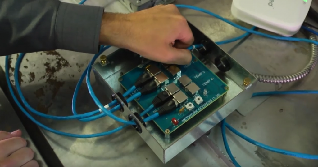
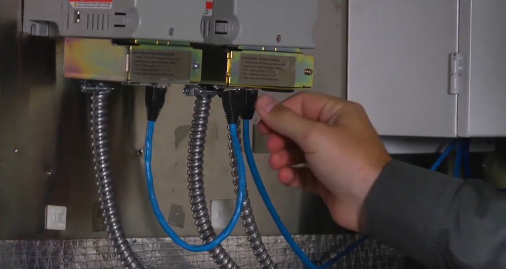
This post covers how to check your Intelli-Hood wiring connections and how to replace a cable. There are several connections that compose the Intelli-hood system, making this a broad subject.
As you review the following video and pictures, please note that cable colors vary by Intelli-Hood system. Learn more about IH1, IH2, and IH3 differences here.
How to Check Intelli-Hood Wiring Connections
First, it is important to verify that all the cables are shielded and tight with no corrosion. Also, check that the output and input are not switched.

Next, begin to check the connections. The connections go as follows:
- Optic cables are connected from the sensor to the Air Purge Unit (APU)
- The APU and temperature sensors are connected to the hood controller and in the correct ports
- The hood controller can be connected to another hood controller if more than one hood is connected to the system. Also, the hood controller is connected directly to the system controller.
- There are also connections that go from the drives to the internal operating processor. If there is a communication issue, it could be from bad connections from the drive or the receptacle. If there is more than one drive, plug the drives one to another in a daisy chain, keeping only one drive plugged to the system controller.
Check also that the motor connections are tight and cables shielded. A loose cable will cause a short especially at the disconnect switch. Water or moisture can also cause the system to trip.
How to Replace Intelli-Hood Wiring
In some situations, replacing a cable can be downright easy. However, applications change from site to site and what should be easy may turn out to be time-consuming. For this reason, it is important that when replacing a cable, you are familiar with the system and how it’s set up. If you are uncomfortable with replacing a cable, you should contact Melink or your local certified electrician.
- When replacing any cable in the system, it is important to determine how it is run. Some sites will have cables inside conduit for every run, and some will have conduit only around the hood area. For systems with multiple hoods or hood controllers, there is a cable that will run between the controllers. For these situations, you may need to have your own termination tools, fish tape, and possibly a second set of hands. Some recommend using the original cable you are removing to pull the new cable. Others recommend using fish tape to avoid kinking or breaking the new cable; they adhere or tape it to the old cable, pull it through the conduit, and then use the fish tape to pull the new cable. When replacing a cable, you should be cautious not to make hard bends or kinks with the cable and not snag the RJ-45 connectors on the ends. Breaks in the shielding can allow unwanted noise from external RF signals and nearby equipment to cause faults in the system.
- For the Intelli-Hood 3 system, the cables connecting the individual sensors and control boards are made of 24AWG 4-pair, Plenum-rated, and shielded Category 5E cable. These cables are available premade/terminated in several common lengths, as well as in bulk for uncommon runs from our Intelli-hood Technical Support.
- Common cables that need checked when you have faults are the optic emitter and receiver cables, the temperature probe cables, VFD cables, and the hood controller cables.
- The optic cables and temp probe cables run to a hood controller and are typically between 5 to 15 ft., depending on the hood size and hood controller location. One hood controller can accept up to four temp probes but only one optic emitter/receiver. From the hood controller to the system control cabinet, there is a “home run” cable. This cable connects the system controller to the hood controllers and all sensors in this chain. There can be multiple home run cables for systems with many hoods, and you will need to verify that you have the correct chain.

- The variable frequency drives (VFD) are also connected to the system controller with cables at the VFD network ports. The VFD network ports can have several VFDs on each chain but one home run for each. Normally VFDs are mounted in a bank of sorts and will daisy together in series using the same cable in a shorter length.
Access Intelli-Hood reference materials, FAQs, and how-to videos. For advanced troubleshooting, contact Melink Technical Support (available 24 hours a day, 7 days a week) via web request or by calling 877-477-4190.