Understanding Your Intelli-Hood VFD

Melink’s Intelli-Hood® controls modulate the speed of the exhaust and fan motors with variable frequency drives (VFDs). Understanding and knowing how to troubleshoot your Intelli-Hood VFD will make maintenance easier.

The VFDs receive commands from a central controller, which receives its input from the optic and temperature sensors. This post will cover Intelli-Hood’s VFD locations, connections, faults, and troubleshooting.

If you are looking for information on Intelli-Hood optic and temperature sensor troubleshooting, click here.

VFD Locations

The Intelli-Hood’s VFDs are located in a variety of spots, and this will vary from site to site. Some common locations are:

  • End cabinets connected to the hood
Intelli-Hood VFD located in end cabinet mounted to hood
  • Remotely mounted cabinets located in or near the hood
Intelli-Hood VFD located in or near the hood
  • Maintenance or electrical room where service breakers can be found
Intelli-Hood VFD located in mechanical room
  • Above the hoods where the lines for the exhaust fan motors have already been run
  • On the roof (Some facilities require NEMA 3R enclosures, which are waterproof and meant for mounting outside the building. Commonly these units are placed near each fan/motor.)

Verifying VFD Connections

Intelli-Hood VFD connections will also vary depending on the facility and types of drives used. There are generally two options: direct control by the Intelli-Hood system via the Cat5e modbus connection or analog control via the Intelli-Hood system.

The modbus control uses our VFD port on the controller and provides 2-way communication with the drive. This allows the actual drive status/data to be displayed on the Intelli-Hood touchpad. If your IH3 touchpad is displaying “VFD Lost Comms,” it usually means the drive has lost power or the connection has been broken, either physically or by some programming change. Verify the Cat5e cable is securely connected at the drive and system controller and if further investigation is needed, contact our technical support for assistance.

If you have an analog-controlled drive, this normally means the drive was either existing or supplied by others and could not be directly controlled by the Intelli-Hood system. In this case, we are telling the drive when to turn on and how fast to go with analog wire connections but do not receive any feedback data showing drive status or faults. In most cases, when a problem occurs with a fan, you have noticed because the kitchen is noticeably quieter or getting hot and smokey. To check the connections, you will need a multi-meter to check DC voltage and continuity. You will likely want to have your facilities team or electrician look into the issue.

Understanding VFD Faults

The VFD is in place to modulate and protect the motor against incoming power from the service breaker to the VFD and from the VFD to the serving motor.

If a fault is detected, cycle power at the service breaker for approximately 1 minute. The display on the VFD should go blank at this time. After 1 minute, turn the breaker back on and cycle the power to the Intelli-Hood system. If the fault persists, contact Melink Technical Support.

VFD Troubleshooting

The following are examples of advanced troubleshooting you may be able to perform on site. However, if you are uncomfortable working with electrical equipment, contact Melink or your local licensed electrician.

Over Voltage Faults: Check for water in the disconnect. Adjusting the deceleration scale on the VFD may help this issue from motor regeneration on the BUS voltage.

Overload Faults: Check the motor nameplate FLA, VFD Programmed FLA, and the actual AMP draw. If over-amping occurs, reduce the maximum frequency from what is currently programmed. This would suggest that the motor is working harder either due to age, belts that are too tight, or a combination of both.

Under Voltage Faults: Check for voltage on all three phases to make sure that all three legs are steady and at the appropriate voltage. This fault may be caused due to a temporary voltage drop from dirty power or loose connections.

Earth Faults: Check for ground connections. Also check the motor for insulation leaks and proper grounding.

Special Notes for Intelli-Hood VFD Faults

VFD issues are the most common Intelli-Hood troubleshooting issues. For advanced troubleshooting, contact Melink Technical Support. Depending on the circumstances, issues may be resolved through phone support, remote diagnostics, remote control, or a technician may be dispatched to test and replace components based on field conditions.

Access Intelli-Hood reference materialsFAQs, and how-to videos. For advanced troubleshooting, contact Melink Technical Support (available 24 hours a day, 7 days a week) via web request or by calling 877-477-4190.

Intelli-Hood Fault Codes: Optic & Temperature Faults

In this post, Melink Technical Support shares tips for diagnosing common Intelli-Hood fault codes. We primarily will cover faults common to Intelli-Hood® optic and temperature sensors. (If you are looking for information about VFD faults, click here.)

Please note that fault codes caused by optic and temperature sensors will NOT stop a kitchen from operating. However, they will cause the hood fans to run at full speed until the fault is cleared. Until they are resolved, the system will not save energy.

Getting Started

If your system has a fault code, it is important to determine which version of Intelli-Hood you have. Fault codes and how they are displayed vary among IH1, IH2, and IH3 systems. For instance, IH1 uses a combination of a numeric display and bar graph. The bar graph will light up to report which sensor is experiencing an issue.

To diagnose faults, consult your product’s reference guide. Click to download for IH1, IH2, or IH3. Please note that everyday kitchen staff should not be expected to understand these faults; the intention is for a contractor or electrician to handle fault issues. After consulting your system’s reference guide, if you cannot determine the fault or need additional help, contact Melink.

Common Intelli-Hood Fault Codes

Melink Technical Support shares the most common Intelli-Hood fault codes:

F4 = This code signals a loss of power. The system will display this code whenever the power is disconnected.

F5 = This is a very common code relating to an internal voltage issue. In about 75% of cases where this code is seen, the system drive is going bad. The other 25% is caused by a bad connection, bad motor, or bad curb voltage.

F7 = F7 is directly related to the motor. When the motor exceeds its pre-programmed motor limit, the error is displayed. It is caused by something causing express resistance to the motor such as an over-tightened belt, the motor bearings wearing out, or something caught in the fan blades.

F8 = This is a common variable frequency drive (VFD) fault code, signaling when the heatsink goes over a certain temperature. A common cause of this is buildup in the system. (The VFD has a cooling fan that needs to be checked periodically to make sure it’s not clogged.) In some cases, the buildup can be removed with compressed air. In extreme cases where the VFD is totally filled with grease, you have to replace the drive.
Example: An IH2 customer reported that their system was overheating and displaying an F8 error. Upon inspection, the cooling fan was caked with a brown powder. There was a hot cocoa station near the system, and cocoa powder was being sucked in through the cooling fan. The cocoa dust was blown out, the fan cleaned, and the system resumed its normal operations.

F12 = This code signals that something is exceeding the system’s drives over all limitations. Motor issues normally cause this code to appear. The motor could be dead or dying. The support team has also seen this in cases where someone replaced the motor but used the wrong size.

F13 = This means there is a direct short to the ground somewhere, and the drive is protecting itself by throwing out an error code. On the motor side, one of the legs or wires is touching ground or arcing to ground when it fires up.
Example: A customer unsuccessfully tries to reset the system on his/her own to clear a fault, does not contact Melink’s Technical Support, and the system results in the same fault over and over again.

F33 = This code relates to the automatic restart limit, which is predetermined at five resets. You will see this code when the drive has attempted to restart itself and hit the same fault five times consecutively.

Special Notes for Intell-Hood Fault Codes
  • The IH2 system uses a coding system on its touchpad to signal faults. Click here for further instruction on IH2 faults.
  • The IH3 fault code system is the most detailed; it displays full error codes on its LCD touchpad. Some of the terminology may be confusing to customers. Click here for further instruction on IH3 faults.

Access Intelli-Hood reference materialsFAQs, and how-to videos. For advanced troubleshooting, contact Melink Technical Support (available 24 hours a day, 7 days a week) via web request or by calling 877-477-4190.

Intelli-Hood Wiring

This post covers how to check your Intelli-Hood wiring connections and how to replace a cable. There are several connections that compose the Intelli-hood system, making this a broad subject.

As you review the following video and pictures, please note that cable colors vary by Intelli-Hood system. Learn more about IH1, IH2, and IH3 differences here.

How to Check Intelli-Hood Wiring Connections

First, it is important to verify that all the cables are shielded and tight with no corrosion. Also, check that the output and input are not switched.

Intelli-Hood wiring connection points
Make sure the cable connections are not loose.

Next, begin to check the connections. The connections go as follows:

  • Optic cables are connected from the sensor to the Air Purge Unit (APU)
  • The APU and temperature sensors are connected to the hood controller and in the correct ports
  • The hood controller can be connected to another hood controller if more than one hood is connected to the system. Also, the hood controller is connected directly to the system controller.
  • There are also connections that go from the drives to the internal operating processor. If there is a communication issue, it could be from bad connections from the drive or the receptacle. If there is more than one drive, plug the drives one to another in a daisy chain, keeping only one drive plugged to the system controller.

Check also that the motor connections are tight and cables shielded. A loose cable will cause a short especially at the disconnect switch. Water or moisture can also cause the system to trip.

How to Replace Intelli-Hood Wiring

In some situations, replacing a cable can be downright easy. However, applications change from site to site and what should be easy may turn out to be time-consuming. For this reason, it is important that when replacing a cable, you are familiar with the system and how it’s set up. If you are uncomfortable with replacing a cable, you should contact Melink or your local certified electrician.

  • When replacing any cable in the system, it is important to determine how it is run. Some sites will have cables inside conduit for every run, and some will have conduit only around the hood area. For systems with multiple hoods or hood controllers, there is a cable that will run between the controllers. For these situations, you may need to have your own termination tools, fish tape, and possibly a second set of hands. Some recommend using the original cable you are removing to pull the new cable. Others recommend using fish tape to avoid kinking or breaking the new cable; they adhere or tape it to the old cable, pull it through the conduit, and then use the fish tape to pull the new cable. When replacing a cable, you should be cautious not to make hard bends or kinks with the cable and not snag the RJ-45 connectors on the ends. Breaks in the shielding can allow unwanted noise from external RF signals and nearby equipment to cause faults in the system.
  • For the Intelli-Hood 3 system, the cables connecting the individual sensors and control boards are made of 24AWG 4-pair, Plenum-rated, and shielded Category 5E cable. These cables are available premade/terminated in several common lengths, as well as in bulk for uncommon runs from our Intelli-hood Technical Support.
  • Common cables that need checked when you have faults are the optic emitter and receiver cables, the temperature probe cables, VFD cables, and the hood controller cables.
  • The optic cables and temp probe cables run to a hood controller and are typically between 5 to 15 ft., depending on the hood size and hood controller location. One hood controller can accept up to four temp probes but only one optic emitter/receiver. From the hood controller to the system control cabinet, there is a “home run” cable. This cable connects the system controller to the hood controllers and all sensors in this chain. There can be multiple home run cables for systems with many hoods, and you will need to verify that you have the correct chain.
Creating a daisy chain between
Daisy chain between variable frequency drives (VFDs)
  • The variable frequency drives (VFD) are also connected to the system controller with cables at the VFD network ports. The VFD network ports can have several VFDs on each chain but one home run for each. Normally VFDs are mounted in a bank of sorts and will daisy together in series using the same cable in a shorter length.

Access Intelli-Hood reference materialsFAQs, and how-to videos. For advanced troubleshooting, contact Melink Technical Support (available 24 hours a day, 7 days a week) via web request or by calling 877-477-4190.

Intelli-Hood Cleaning

To maintain your kitchen’s system, regular Intelli-Hood cleaning is important. If general cleaning is not performed, the Intelli-Hood® system’s optic sensors can trigger a fault and will operate the fans at 100%, thus eliminating any opportunity for energy savings. Below we will cover tips to clean the temperature sensors, optic sensors, hood exterior, and touchpad.

Most system damage is related to improper cleaning. Before any cleaning procedure, it is important to consult your system’s reference guide. The general optic and temperature sensor guidelines below apply to all systems (IH1, IH2, IH3).

Cleaning the Optic Sensors

The most common Intelli-Hood cleaning issue is owners not taking proper precautions to protect the optic sensors. Each set of optics has an emitter and a receiver; these pieces have a resilience coating to protect them from general moisture. For Intelli-Hood to function properly, site staff needs to keep the optics clear of obstructions and clean the optic sensors periodically with non-abrasive, non-corrosive cleaning products. We recommend only using a mild cleaning detergent, such as Dawn dishsoap.

Cleaning Intelli-Hood optic sensors and emitters
Intelli-Hood Optic Sensor Box

How often should I clean? The time between cleanings is largely dependent on the volume of grease being exhausted. Optic sensors in kitchens with lots of grease-cooking may need to be cleaned several times a month. On the other hand, some kitchens may have sensors that can go several months between cleanings.  If sensors get too much build-up on the lenses, an optic fault will occur. The fans will run at full speed until the sensors are cleaned and reset.

How should I clean the optic sensors? Press the push-button latches on the sides of the optic box to remove the cover. Then wipe the lens of the optic circuit board with a soft, damp cloth. Replace the cover of the optic box ensuring that the green cable connecting the cover to the optic bracket is not in front of the lens.

Cleaning the Intelli-Hood optic sensors
Remove the optic box cover to clean the internal components.

Is hood cleaning safe? When performing a general cleaning of the kitchen hood, hood cleaners must be careful to keep the Intelli-Hood components dry. The optic sensors are water-resistant but not waterproof. The optic box should be sealed with thick tape and plastic wrap before using high pressure water, steam, or other cleaning chemicals in the hood. Hood cleaners should not soak any parts of the system. Harsh cleaning chemicals can lead to scratching of the optic lens. Care should be taken around the fire suppression device (ANSUL pipes) when cleaning; sometimes when cleaning, these can shift the placement of the optic sensors.

Cleaning the Temperature Sensors

Temperature sensors are encased by a round cylinder to help prevent contaminant buildup on the sensor itself. They rarely need to be cleaned.

Intelli-Hood cleaning temperature sensors
An Intelli-Hood temperature sensor

However, if extremely large amounts of grease or other contamination build up on the sensor, the probes should be brushed or wiped clean with a soft cloth. Do not wipe down the temperature sensors with force; it is not necessary for them to be absolutely spotless.

Pressure cleaning is not recommended. If water soaks the temperature sensors, the water will work its way back through the threads, reaching the center of the Intelli-Hood processor.

Cleaning Intelli-Hood’s Electrical Components

Touchpad: The touchpad may be wiped clean, but it should not be soaked with excessive water. If the face is damaged, special care must be taken to prevent water from getting through the label to the electronic components behind the face. 

Cleaning Intelli-Hood touchpad with soft cloth
Clean Intelli-Hood’s touchpad with a soft cloth.

If holes start to wear in the touchpad’s keypad, contact Melink for replacement parts. You may need to replace the labels or the entire touchpad, depending on the damage. If you do not fix the holes, the internal parts may get wet, eventually leading to system failure and kitchen downtime.

If a touchpad is replaced, caulk should be used to seal the backside. This sealant will help protect the touchpad from kitchen cleaners that are sprayed in its vicinity.

Hood Light Fixtures: The hood light fixtures must be kept dry, too. If water gets inside a light fixture, it could create a short on the circuit and damage the Intelli-Hood processor, which powers the lights.

End Cabinet: If an end cabinet is present, take care to avoid getting components on the inside wet. Generally, these cabinets are completely open from the top. 

Cleaning the Hood-Top Equipment

On top of the hood, you may find a number of Intelli-Hood components including the air purge unit, hood controllers, temperature probes, and control cables.  These components must remain dry.

If a hood cleaner or anyone else needs to be on top of the hood for any reason, they must be careful to avoid stepping on these components in order to keep them dry.

Access Intelli-Hood reference materialsFAQs, and how-to videos. For advanced troubleshooting, contact Melink Technical Support (available 24 hours a day, 7 days a week) via web request or by calling 877-477-4190.

Which Intelli-Hood is in My Facility? How to Identify Intelli-Hood Systems

How can a facility manager identify Intelli-Hood systems at his or her various properties? Different systems may be installed, and each system has its own unique reference guide and troubleshooting tips.

Background

Over the years, Melink Corporation has designed and implemented three Intelli-Hood® systems: IH1, IH2 and IH3. Each system has its own specific configurations. While all work on the same basic principles, they DO NOT have the same parts or interfaces.

So how can you determine which system is in your facility? You can determine this by physical attributes and the system’s serial number. Watch our how-to video and consult the steps below…

How to Identify Intelli-Hood Systems

There are three methods to identify your Intelli-Hood system:

Serial Number

The serial number is the absolute best way to identify your system version. On the inside of the system’s panel door, you will see the unit’s serial number. The color of the label may vary, depending on your system. IH1 normally has a white label, whereas IH2 and IH3 have blue labels.

As for the numbers themselves, IH1 systems began with serial V1000 or V001000 and continued until the late V3999 numbers. IH2 serial numbers started at V4000 or V004000 and counted up from there.

Identifying your Intelli-Hood System by IH1 and IH2 serial numbers

At the beginning of IH3 we changed the starting point slightly and began with V300000. All serial numbers in the V300000 and V400000 are IH3.

Identifying your Intelli-Hood System by IH3 serial numbers
Cable Colors

Cable colors are different among systems. If your system has white/grey cables, it is an IH1. If your system has blue cables, it is IH2. Green cables signal IH3.

Touchpads

The main touchpad on the kitchen hood can distinguish your system.

IH1 has a single digit “HOOD” display.

Intelli-Hood IH1 display

IH2 has a four-digit “HOOD” display.

Intelli-Hood IH2 display

IH3 is our first system with a full LCD display.

Intelli-Hood IH3 display

Knowing Your System

To accurately troubleshoot system issues and to order replacement parts, you must supply the Melink Technical Team with your system model (IH1, IH2 or IH3). Most issues can be solved over the phone with a facility manager and/or contractor capable of performing the work on site.

If you are purchasing replacement parts and you are not on site, please verify the system model with the site beforehand. If the system model cannot be verified, Melink cannot guarantee the replacement parts are correct. There is a restocking fee for parts ordered in error.

If you cannot determine which system you have, Melink Corp does maintain an internal database. However, we cannot guarantee your facility is in the database. Frequently, restaurant sites change ownership and names. For instance, what was once “Joe’s BBQ” may now be known as “Bob’s BBQ.” If no one has contacted Melink to update the original site name, it will not be searchable in the database.

Access Intelli-Hood reference materialsFAQs, and how-to videos. For advanced troubleshooting, contact Melink Technical Support (available 24 hours a day, 7 days a week) via web request or by calling 877-477-4190.

Intelli-Hood System Basics: Using the Touchpad

The Intelli-Hood® touchpad is the primary user interface of the system. Every Intelli-Hood is equipped with at least one touchpad; some systems have multiple touchpads. Touchpads vary by system model; consult this guide for help determining your system. In this post, we will focus on the IH3 touchpad.

IH3 Touchpad Navigation

Fans Button: The Fans Button is typically used to change the state of the system between “Standby Mode” (exhaust fans off) and “Energy Saving Mode” (exhaust fans running).

Lights Button: This turns the lights of the hood on and off. This function is optional and may not be used in all applications of Intelli‐Hood. Consult the design documents for your system to determine if this button is used.

Soft-Key Buttons: Two soft-key buttons below the display screen can be used to navigate functions displayed on the screen. In normal operation modes, the right button is used to access programming and help menus, and the left button is used to active the “100% Fan Speed Mode.” These functions vary when the user is navigating the program settings.

Arrow Buttons: The two arrow buttons are used to scroll through configuration parameters and can be used to change programming values.

Status Screen: The status screen shows the operational state of the Intelli‐Hood system.

Faults Screen: The faults screen shows active system faults that need addressed. Once a fault is cleared, it will no longer be displayed here.

IH3 System Modes

In Standby Mode, the fans will be off and users will see the Intelli‐Hood logo splashscreen. The right soft key can be used to enter the menu.

In Energy Saving Mode, at least one fan associated to the touchpad is in Energy Saving Mode. This may not pertain to all fans. The display will scroll through the hoods and fans that are active and display their respective operating speeds. The left soft key can be used to send the system to 100% or Bypass Mode, and the right soft key can be used to enter the menu.

In 100% or Bypass Mode, the display will scroll through the hoods and fans and display their respective operating speeds. The left soft key can be used to send the system into “Normal” Energy Saving Mode, and the right soft key can be used to enter menus.

In the Menus Home Screen, the user can locate System Status, System Configuration, the Help Menu, and the About Menu.

Intelli-Hood touchpad menu navigation

IH3 Menus

System Configuration Menu: This is where the system can be configured by adjusting the number of hoods, fans, and many other parameters. The System Configuration Menu will be locked with a specific pass-code in order to prevent accidental modification of system parameters. Users should not attempt to modify the configuration without the help of a certified Intelli-Hood professional.

Help Menu: The Help Menu contains instructions for how to contact your local rep or the manufacturer for technical support and other information.

About Menu: The About Menu simply provides system information such as the firmware version, serial number, IP address, date, and time.

Intelli-Hood Touchpad Maintenance

Most damage to the keypad is related to cleaning. Do not clean the touchpad with any harsh or abrasive chemicals. If the surface needs to be cleaned, use a mild dish detergent like Dawn dishsoap. If holes start to wear in the touchpad, contact Melink for parts to replace the labels or the touchpad itself. This is to avoid the internal parts from getting wet, potentially leading to kitchen downtime.

Intelli-Hood Touchpad Troubleshooting

If your touchpad screen is frozen, the system has most likely “lost” its configuration. Contact Melink Technical Support so that the appropriate configuration can be reloaded. 

If your touchpad is frozen and it is not a configuration issue, you may want to verify that the LEDs on the circuit board are illuminated.  Power the system down at the controller and pull the cell battery off the baseboard, replace the battery, and turn the system back-on.

Access Intelli-Hood reference materials, FAQs, and how-to videos. For advanced troubleshooting, contact Melink Technical Support (available 24 hours a day, 7 days a week) via web request or by calling 877-477-4190.

Intelli-Hood System Basics: Operational Modes

There are four Intelli-Hood® system operational modes: Energy Saving, Standby, 100% (Bypass), and Emergency Fire. The Intelli­-Hood HVAC controls package visually monitors the level of cooking activity and automatically instructs the exhaust fan to operate only as fast as necessary to save energy. Learn the basics about each operational mode…

Energy Saving Mode

First, Energy Saving Mode is the operational state when one or more exhaust fans are on. In most cases, all exhaust fans controlled by Intelli-Hood will be in Energy Saving Mode at the same time. However, in some configurations, it is possible that some fans will be in Energy Saving Mode while others remain in Standby.

Standby Mode

In Standby, the exhaust fans are not operating, but Intelli-Hood is monitoring temperature and optic sensors.  The system’s touchpad is typically used to manually change the mode of the system between Standby and Energy Saving Mode. Depending on both cooking conditions and pre-programmed settings, it is possible for Intelli-Hood to automatically change modes.

100% Mode (Bypass Mode)

Next is 100% Mode, which is commonly referred to as Bypass Mode. This mode is a secondary function. Typically, Intelli-Hood is set to appropriately send the exhaust fans to full speed based on conditions detected by temperature and optic sensors.  Kitchen staff has the ability to send fans to full speed by placing the system into 100% Mode when it is operating in Energy Saving Mode. 100% Mode is a timed function with a default expiration time of ten minutes.  After the timer expires, fans will revert back to Energy Saving Mode.

Emergency Fire Mode

Lastly, the Emergency Fire Mode is triggered by the fire suppression system. This mode is activated when the main power to the Intelli-Hood is removed. In this mode, the touchpad and sensors will have no power or function.

Access Intelli-Hood reference materials, FAQs, and how-to videos. For advanced troubleshooting, contact Melink Technical Support (available 24 hours a day, 7 days a week) via web request or by calling 877-477-4190.

National Cut Your Energy Costs Day: Tips for Businesses

In the United States, January 10 is National Cut Your Energy Costs Day, a time that encourages people to look for ways to reduce energy usage and ultimately save on energy bills.

Melink offers five tips for businesses to cut their energy costs. Implement these solutions today to impact your business’ bottom line in the future!

Melink technician checking air flow in business for energy costs

Tip #1 — Ensure Your Building Has a Balanced Airflow

An air balance testing service is the process by which the performance of HVAC airflow is measured.  Once it is tested, the systems are then adjusted, or balanced, so that the air brought into a building is slightly greater than the air being pulled out of the building. The result is a comfortable, healthy indoor environment with an HVAC system that is optimized to perform efficiently. Read more air balance basics.

Keep in mind there are different degrees of air balance reports and you should choose an air balance contractor wisely. Not every balancing firm performs the same service or provides the same report at the end of the project. Hire a professional, certified firm like Melink Corporation.

Energy costs in busy commercial restaurant kitchens

Tip #2 — Conserve Energy in Commercial Kitchens

If your facility has a kitchen operation, this is an area where you can greatly reduce your operating costs, as well as occupant comfort. Consider installing a demand control kitchen ventilation (DCKV) system to control the variable speed of your kitchen’s exhaust fans.

Traditionally, kitchen exhaust fans run at 100% speed for constant periods of time.  With the addition of a variable speed system, like Melink’s Intelli-Hood®, fan speeds are reduced when cooking isn’t at its maximum. 

Dirty furnace filters can increase energy costs

Tip # 3 — Replace Used Furnace Filters

This may sound like a simple fix, but dirty furnace filters can lead to defective equipment, airflow issues, and ultimately higher energy bills. If a filter is clogged, airflow is reduced and the unit(s) will have to run longer to achieve the desired temperatures. Seasonally changing air filters within your building is one of the easiest, cheapest, and most effective ways to ensure maximum airflow output.

Monitor your building for guests' comfort and to watch energy costs

Tip # 4 — Monitor Your Building

Monitor your building’s health BEFORE a costly issue develops, such as mold growth, high energy bills, safety issues, or comfort issues for occupants. Melink offers PositiV®, a standalone tool to monitor your building’s performance data. A small investment now can lead to a great reduction in future energy costs.

Rooftop HVAC Unit

Tip # 5 — Have a Replacement Plan

Whether your facility has an immediately aging HVAC unit or not, it’s important to plan for the future — especially with the phase-out of R-22. Emergency replacement, AKA “fix-on-fail,” is the costliest way to repair units. If you implement a proactive equipment replacement program, you can save approximately 70% per unit, which adds up to major energy cost savings.

National Cut Your Energy Costs Day may only happen once a year, but Melink offers energy-efficiency solutions for businesses year-round. With Melink, cut your commercial building’s energy costs. Contact us today at (513) 965-7300.

Using Data to Evaluate Building Health

What is the most valuable resource in the world? If you said time, I can’t argue with that… However, if you said a commodity like gold, coal, or even oil, you may be shocked to learn that not even these precious natural resources compare to the inherent value of a certain intangible object. I’m talking about data — more specifically, the data that allows us to make mission-critical decisions about building health.

We live in a period known as “The Digital Revolution,” where the once groundbreaking mechanical inventions of the 20th century have been enhanced by the digitization of computer software and automated control systems. Bookkeeping now consists of populating Microsoft Excel worksheets, medical records are now analyzed by computers, and checks can now be deposited with a smartphone camera. These advances in technology have, without a doubt, made our lives easier. However, many of us are overlooking the most valuable byproduct of using these machines, which is the collected data itself.

The practice of interrelating computing devices for the sake of transferring data over a digital network is known as the Internet of Things (IoT). This shared system of information allows us to collect data using multiple machines to ultimately assist humans in making better decisions.

Melink Corporation has always strived to be ahead of the curve when it comes to modernizing its products for better data acquisition.

For instance, our Intelli-Hood® kitchen ventilation system was the first of its kind back in the early 1990s. Our engineers have since continued to evolve its firmware to better integrate with building automation systems so that building owners can more closely monitor energy consumption. Users can log in to a cloud-based portal to extract real-time data to better manage their utilities. Thirty years after its inception, Melink continues to lead the industry by advancing green energy building solutions.   

In February 2019, Melink Corporation pushed the envelope for how building owners keep their workspaces healthy by launching a new product that is the first of its kind. Much like how a smartwatch can closely monitor your physical health, PositiV™ is a device that monitors your building’s health.

Components of building health
Melink Corporation’s PositiV™ system helps monitor building health.

About the size of a thermostat, PositiV ™ houses a variety of sensors to detect temperature, relative humidity, CO2 levels, and building pressure. This data is collected and transferred to our online portal where users can view the live data and trend it over time. For facilities managers who operate a network of buildings across multiple cities and states, PositiV™ allows them access critical data that can both justify costly HVAC improvements and warn against sick building syndrome. How is this possible? Melink’s software developers have implemented machine-learning algorithms and data visualization tools to harness the full potential of this invaluable building health data. After all, data means almost nothing if it’s not thoroughly analyzed and effectively interpreted.

Similar to how doctors check blood pressure, cholesterol levels and body temperature to diagnose a patient, PositiV™ can connect seemingly unrelated data sets to draw conclusions about building health.

Building owners, feel more empowered to make the critical decisions you need to keep your occupants comfortable.  Calculate how PositiV™ can help you save money and improve building health.


The Advantages of Optical Sensing in Demand Control Kitchen Ventilation Systems

As the inventors of demand control kitchen ventilation for commercial kitchen systems over 25 years ago, Melink is solely focused on providing maximum energy savings with safe and reliable controls for our customers with our Intelli-Hood® system. Not surprisingly, we’ve learned a lot of things over these years and continuously improve our controls based on lessons learned, industry trends, best practices, technological advances, laboratory and field research. Our industry leader status makes us a ripe target for competitors and naysayers, to which we welcome and enjoy engaging in a healthy debate to advance the usage of demand control kitchen ventilation across the globe.  To this end, I would like to address a document produced by a manufacturer and a respected goliath in the kitchen ventilation industry. 

*All text in red is directly taken from a Captive-Aire produced document obtained by Melink*

The Captive-Aire Demand Control Kitchen Ventilation (DCKV) system controls the fan speeds based on heat generated from the cooking appliances in comparison to the room temperature. Captive-Aire has done extensive research into the effectiveness and practicality of sensing smoke to override the system and turn on the fans. Melink offers an optic sensor inside the hood, which, if penetrated by smoke, will automatically turn the fans to high speed. This is one of the primary differences between Melink and DCKV. 

Melink has performed extensive research over the years into various sensing methods, including space temperate versus hood canopy sensing (delta T) methods, and fallacies discovered in the delta T method is what led us to the patent for utilizing optical sensors in conjunction with heat sensing. Our research uncovered many external factors in the kitchen environment that caused false readings including cross drafts, supply air configurations, door openings and seasonal temperature changes that could trick the system into a cooking response and eliminate energy savings.

Another challenge in the temperature only approach is determining the level of cooking based on these temperature changes alone as the cooking effluent (smoke, steam, etc) often presents itself before a strong thermal plume on the temperature sensor. For example, if you place a cold hamburger patty on a grill the temperature will initially reduce as the heat transfers into the food while creating effluent that must be captured by the hood.  Systems reliant upon temperature only are slow to react to this change and you are left with two options; decrease the temperature range of the system so it runs full speed at the slightest presence of heat (diminishing any energy savings), OR don’t effectively capture the effluent in the hood canopy and cause smoke rollout.  As we at Melink like to say, “You can’t capture what you can’t see.” 

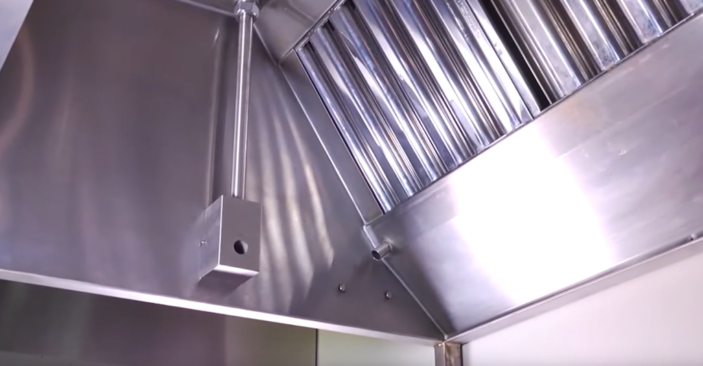
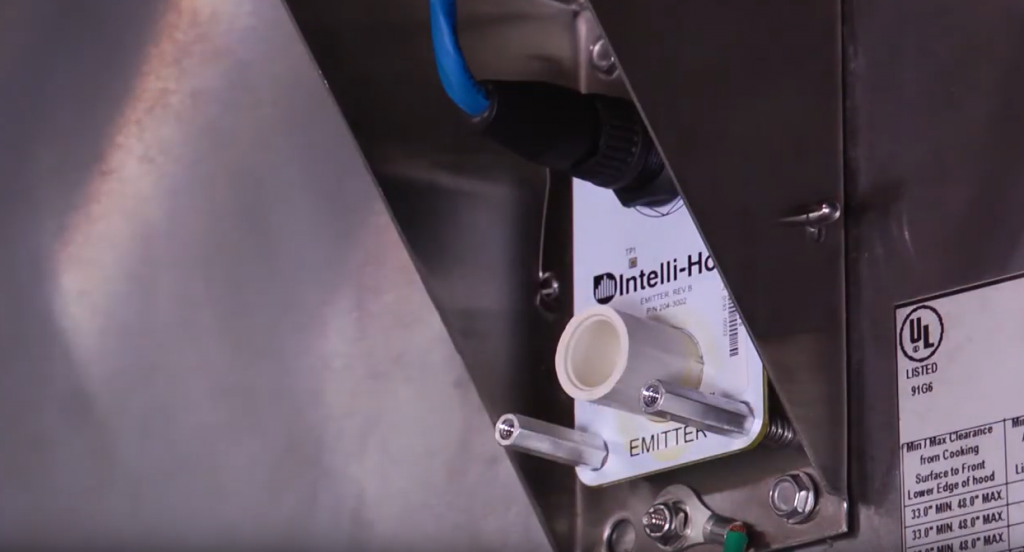
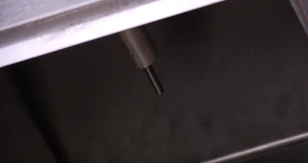
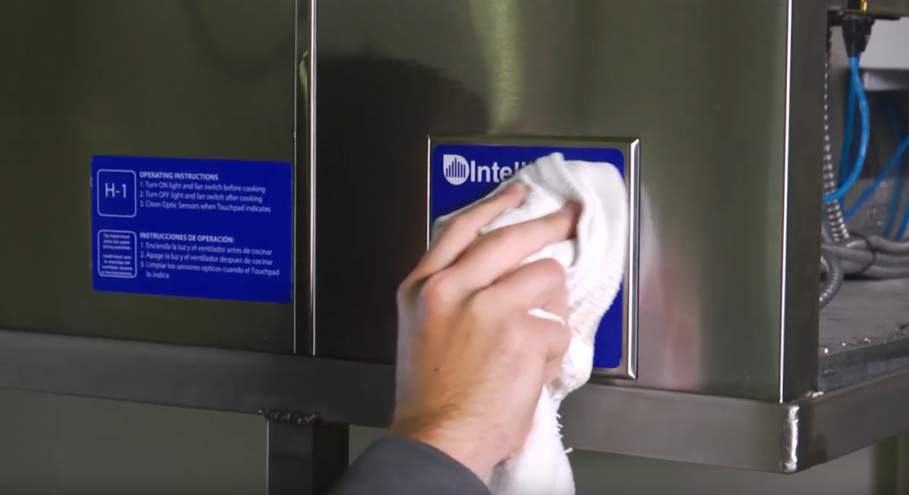
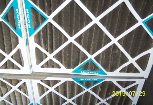
We have found that using an optic sensor to sense smoke is very problematic. When installed inside a greasy exhaust hood, the lens will tend to get caked with grease. This will cause the fans to run at full speed all the time, and therefore eliminate your energy savings. As a result, Melink installs small fans to continuously blow air at the lens to try and avoid grease particles from landing there. This is another component the needs to be maintained and serviced regularly. These optic lenses also require an I/O processor to be wired into the system—this is one more component. If anything happens to the lens, fan, or processor the system will fail. This results in a sustainability issue. Electrical components inside a greasy exhaust hood may not be a sustainable option over the course of several years. The optic sensors/lenses need to be cleaned, and according to the Melink manual, should not be sprayed with hot water or steam by the hood cleaner to avoid damage.

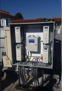
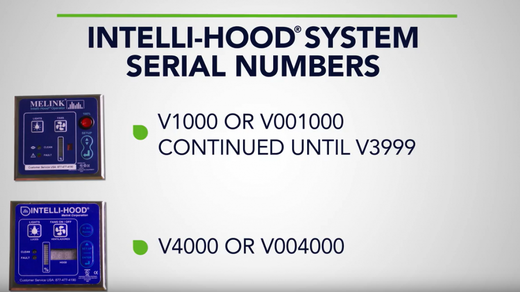
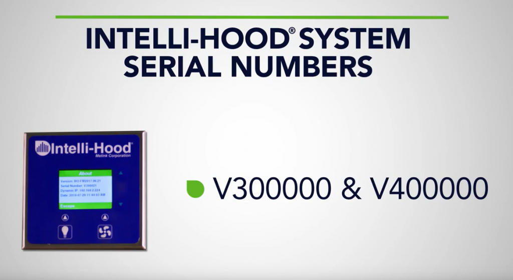
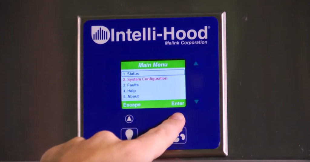
 Yes, our system has a brain and it’s called the System Controller (formerly I/O Processor referenced). All demand control kitchen ventilation systems have some sort of controller to interpret the signals coming in and we like to think our brain is pretty special.  In fact, unlike most competitor systems that utilize an off the shelf PLC controller we custom design ours for the sole purpose of saving you energy in the kitchen and integrating into your building.  Our System Controller is native BACnet (IP), internet ready, 4G wireless capable and has the brainpower to control up to (39) kitchen hoods and (64) exhaust or supply fans. 

We do utilize a component called the Air Purge Unit (APU) that contains a 12VDC fan to direct airflow into the optic housing to maintain a positive pressure environment to alleviate grease buildup.  However, kitchens can be harsh environments and depending on the appliance type underneath these could benefit from a monthly swipe with a clean cloth if it’s above a high grease producing appliance, but less intensive appliances mean less cleaning.  Fortunately, we use that big brain of ours to automatically re-calibrate the optics every day based on cleanliness for optimal performance and if it gets too dirty the system will alert you via the Touchpad or email as to which hood may need cleaned.  

Additionally, a typical Melink system costs much more than a Captive-Aire DCKV so the payback period for a Melink system is much longer.

Not necessarily, the formula for the simple payback period is the initial project cost divided by the annual savings to determine at what time the investment breaks even. If a more intelligent system can save 3x the energy of temp-only system, then the simple payback periods are equal. The downside of this metric is the failure to account for the time value of money and consideration of cash inflows beyond the payback period.  It’s important to look past first cost and take into account the full savings yielded over the life of the system and perform life cycle cost analysis. 

For example:

        Temp-Only System

  • First Cost = $5,000
  • Annual Savings = $1,500
  • Simple Payback Period = 3.3 Years
  • Energy Savings over (7) Years = $10,500
  • Net Savings: $10,500 – $5,000 = $5,50

Melink Intelli-Hood®

  • First Cost = $15,000
  • Annual Savings = $4,500
  • Simple Payback Period = 3.3 Years
  • Energy Savings over (7) Years = $31,500
  • Net Savings: $31,500 – $15,000 = $16,500

Over the life of the systems in this example Intelli-Hood® will yield $21,000 in more energy savings vs. the competitor, less the initial capital difference of $10,000 ($15,000 – $5,000) = $11,000 more in
free cash flow.  This example does not factor in the time value of money.   

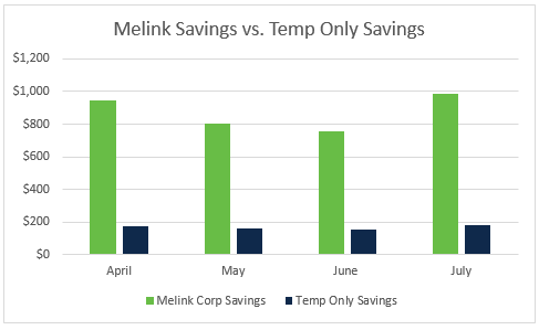
The below data shows the savings difference when a Melink Intelli-Hood® system was installed at a restaurant previously using a temperature only system. The baseline data was provided to the owner by the temp-only hood manufacturer, and we analyzed the electrical and conditioned air savings via our Estimated Savings Report.  Once the Intelli-Hood® system was installed we compared the data and found that Intelli-Hood® system yielded 523% more savings than the previous system. Click here to see real IH performance results.


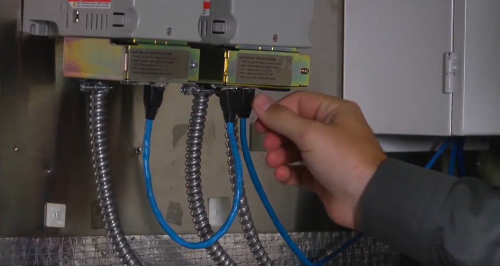
Testing has shown that very sensitive heat sensors are as effective as optic sensors in triggering exhaust fans if heat or smoke is present. If cooking generates smoke, then the cooking process will also generate heat. The heat sensors in the Captive-Aire Demand Control Kitchen Ventilation are easily adjustable as different project and applications may require.

Through our own testing in the lab environment, and more importantly the lab of reality in the commercial kitchen with over 10,000 systems, temperature sensing alone will not allow for a quick response to smoke. Based on our data obtained from an installed temp-only system, the heat sensors appeared to provide no active modulation and acted basically as a two-speed system with an active base speed of 80% and quickly ramping a holding a constant speed of 100% through the day since the appliances were on. Again, without the ability to visually monitor the cooking a temp-only system must be run at much higher minimum speeds as a safety net for capturing effluent. This is a major energy savings penalty.

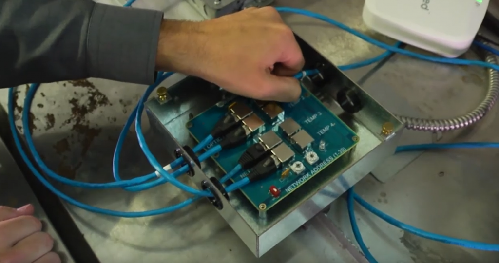
The heat sensors may be “easily adjustable”; however, this requires human manipulation and functional commissioning.  Most often these systems are sent to a mechanical contractor with the instruction to connect the temperature probes to control panel and are left at whatever the default factory setting is.  We like humans too but given the chance we like to engineer around potential issues and lack of consistency from one contractor to the next around the world.  Thus, we patented another feature dubbed “Auto-Temp Span”, which collects performance data from every sensor in the system at defined intervals and automatically sets the optimal temperature spans for every hood in the system.  If the chef decides to change menus, appliances, or a new tenant takes over the space the system will learn these new habits and self-commission for optimal performance.  Call it “machine learning”, call it “artificial intelligence”, we call it a good idea that benefits the end-user.

Lastly, the DCKV has a 100% air override button to send the fans into full speed as a safety precaution.

This override button feature is a code requirement for all demand control kitchen ventilation systems; we have one too.

Here are a few additional differences between Captive-Aire DCKV and Melink Intelli-Hood®:

  • Captive-Aire DCKV is typically programmed with a “prep mode” feature to allow greater energy savings. This feature will run the exhaust fans at a very low speed
    (typically, 20% speed) when the system is first turned on by staff or BAS. This speed is equal to the design differential between exhaust and make-up air. DCKV will run in prep mode until the heat of the appliances necessitates greater exhaust at which point the exhaust and make-up air will both ramp up and cooking mode will commence.
    Melink as currently designed runs both make-up air and exhaust at 50% of its design. 
  • In cooking mode, Captive-Aire designs for a 20% reduction in fan speed during light load cooking times. This reduction is based on extensive research on the topic. Lab testing by The Food Service Technology Center in California has shown that no more than a 20% reduction from a proper design cfm can be made in order to allow the
    system to adequately exhaust appliances when in light load. The Melink system allows for a 50% turndown, therefore, in order for that amount of
    reduction to work properly, the design cfm would have to be increased so the system still works effectively at a 50% reduction. A lower design cfm with 20% fan speed reduction will be more efficient and save more energy than a higher design cfm with 50% fan speed reduction. Captive-Aire DCKV has the ability to provide a 50% turndown, but we do not recommend this. 

From our perspective, this represents nearly a three-speed system with “modes” to make up for the lack of technology, sensors, programming, and algorithms to modulate based on real-time cooking information and optical monitoring, resulting in a loss of energy savings ability. As representative in our data, the temperature spans are typically set so low with these systems, that as soon as any appliances are on, the fans run at an 80% minimum for a very short amount of time and then jump right to 100%.  Unfortunately, it’s pretty rare to see any appliance gas valve regulation in commercial kitchens and most appliances are left at nearly full temperature all day independent of actual cooking, which causes temp-only systems to run at or near full speed all day. We’ve also come across several temp-only systems in the field running at 100% speed when the exhaust temperature read 72 and 73 degrees Fahrenheit.

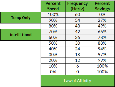
The Melink Intelli-Hood® system is capable of 20-30% minimum speeds as well, but turn-down ratio is a moot point when the rubber meets the road, or when the meat hits the grill in this case.  Our default minimum speed is 30%, a 2% electrical energy difference vs 20%, and we actively modulate through the entire speed spectrum to 100% to maximize energy savings.  The key to electrical energy savings in motor applications lies in the Law of Affinity (below), which at the top of the fan curve roughly translates to a 10% speed reduction = 25% electrical energy
savings. The key to savings with demand control kitchen ventilation is having the optics to safely and actively modulate at the upper ends of the spectrum during the cooking day to maximize savings near the top of the fan curve between 70-100%.


In addition to electrical energy savings from the motor control, Intelli-Hood® also integrates into the make-up air system to modulate based on the exhaust demand.  This modulation provides additional conditioned air savings and can have a significant impact on the payback of the system.  The more extreme the outdoor air environment, the greater the opportunity for energy savings in the reduction of the heating or cooling loads.  The ratio of savings for conditioned air is 1:1 with fan speed reduction, i.e., a 30% reduction in speeds = 30% reduction in conditioned air.

With nearly 20 states adopting ASHRAE 90.1 2010, or higher, energy standards it’s clear that demand control kitchen ventilation is here to stay and we’re proud to have launched this revolution back in 1989.  One of our core values at Melink is Innovation, and we continue day in and day out to develop more advanced commercial kitchen control systems to save our customers valuable money and hopefully make the planet better for our future generations one hood at a time.  Feel free to contact us regarding your next kitchen design involving demand control ventilation or if you’re an existing operator of a commercial kitchen looking to save money, we happen to be experts in retrofits as well.